X-626 Recirculating Water Pump House and Cooling Tower
The X-626 Recirculating Water Pump House and Cooling Tower (i.e., X-326 Process Building cooling system) consists of approximately 2,340 coolant evaporators, 200 coolant condensers, one pump station, one cooling tower, and connecting piping and instrumentation.
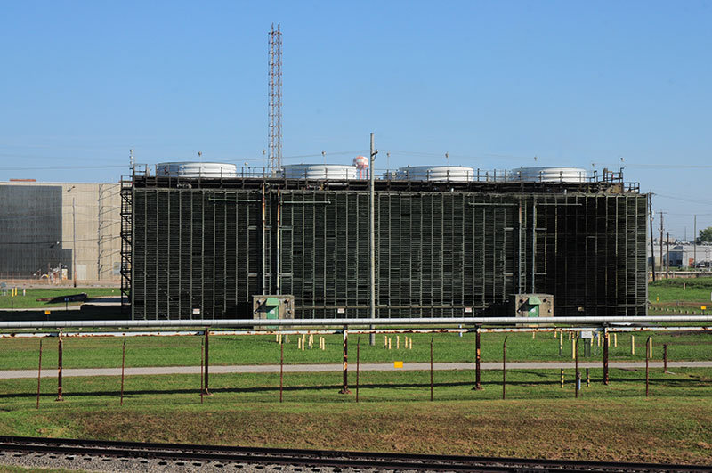
During plant operations, the X-326 Process Building coolant system was similar to the other systems except that one condenser served 12 evaporators. Cooling water was supplied to the condenser through either a 12-, 14-, 16-, or 18-in. header within the X-326 Process Building, and the headers were connected to the X-626 Recirculating Cooling Water (RCW) system by underground 42-in.-diameter pipes. The X-626-1 Pump House (70 ft wide, 115 ft long, and 30 ft high) contains six pumps rated at 8,000 gpm each. All were driven by 2,400 volt, 3-phase, 60-cycle induction motors. The X-626-2 Cooling Tower is an induced-draft, cross-flow tower constructed of redwood. It is segmented into four cells, each with two 20-ft-diameter fans to draw air through the tower. The tower is about 86 ft wide, 145 ft long, and 40 ft high.
During plant operations, the X-626-1 Pump House and X-626-2 Cooling Tower circulated and recirculated water that was used to remove the heat of compression from the process gas, along with waste heat from a few auxiliary processes, and to dissipate this energy to the environment from the X-326 Process Building. They, like systems connected with the X-330 and X-333 Process Buildings, functioned as an independent unit for the most part, but they belonged to an overall plant-wide RCW system.
Each process building’s cooling system contains a primary loop which consisted of Freon-114 that exchanged heat from the process to the Recirculating Cooling Water (RCW) through the evaporation and condensation process and came into contact with the hot Uranium Hexafluoride (UF6). A secondary loop was RCW that received the heat through a heat exchanger and carried it to the cooling towers. In the cooling towers, the heated water in the secondary loop came into contact with cool atmospheric air, which absorbed the heat. The heated air was discharged at the top of the tower and as the cooling water fell through the tower, it was collected in a basin below the tower and then recirculated.
Blowdown water was routed from the X-626 RCW system through the X-630 RCW system to the X-633 RCW system and thence to the X-616 Liquid Effluent Control Facility. The X-626 RCW system was shut down in 2016.
Construction
Completed in 1954
Building Size
Pump House - 70 ft. wide, 115 ft. long, and 30 ft. high
Cooling Tower - 86 ft. wide, 145 ft. long, and 40 ft. high